LTE throughput
In this lab session we'll interactively investigate some of the characteristics of 4G Long Term Evolution (LTE) communication which impact the throughput. This course is provided by Ghent University and iMinds as part of the FORGE project, Forging Online Education through FIRE.
Introduction
You will be using actual hardware (and no simulations) to experiment with different settings and features of LTE (Long Term Evolution, based on 3GPP standards) when deploying your own 4G cellular network. By using this hardware to solve multiple questions in a set of well-thought-out exercise scenarios, you will gain a better insight in the different aspects which impact the achievable throughput of LTE.Live experimentation
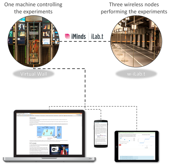
The wireless nodes you will be using are part of the iMinds w-iLab.t Zwijnaarde testbed (a.k.a. "wilab2"), which is physically located at the Zwijnaarde campus in Belgium but can be configured, managed and tested completely from within the web interface you are currently using. This web interface itself is controlling the wireless nodes and is also dynamically created and hosted at the iMinds Virtual Wall testbed, which is physically located at the Zuiderpoort offices (Ghent) in Belgium.
These so called FIRE (Future Internet Research and Experimentation) testbeds can also be used in research projects to collaborate with industry partners to e.g. study and improve LTE functionality. The configuration and experiments that you will perform during this lab session do conceptually not differ from the LTE deployment of your own mobile telecom operator.
The configuration of the hardware at the testbed is automatically done using a process called provisioning. This includes the reservation of machines in the wireless testbed with the appropriate hardware, installing the required operating system and tools, and making these machines available through SSH (secure shell). You can view the status of the required hardware in the box below. You can check the availability and/or ask to start the provisioning process.
Provisioning
Verifying experiment node availability
The experiment nodes are available.
The experiment nodes are not available. Schedule your own lab session using our reservation system and return during your timeslot.
LTE concepts
LTE, an abbreviation for Long-Term Evolution, commonly marketed as 4G ('the fourth generation'), is a standard for wireless communication of high-speed data for mobile phones and data terminals. Compared to earlier 3G technologies (e.g. UMTS/HSPA), it increases the capacity and speed by using a different radio interface together with core network improvements. The standard is developed by the 3GPP (3rd Generation Partnership Project) and was first specified in its Release 8 document series, with additional improvements and features in the succeeding Releases.
The network architecture was redesigned and simplified to an IP-based system with significantly reduced transfer latency compared to the 3G architecture. The decision to go to an all-IP system and leave the circuit-switched (CS) interface (as included in 2G and 3G) out of the LTE specifications might be considered drastic but, on the other hand, it will definitely speed up the process for moving the telecom traffic towards the packet-switched (PS) domain, which supports the idea of delivering most communications over IP, including the voice service.
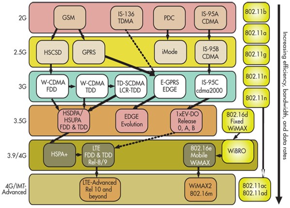
The LTE wireless interface is incompatible with 2G and 3G networks, so it must be operated on a separate wireless spectrum. Both typical European cellular evolution paths (GSM-GPRS-WCDMA-HSPA, described in earlier 3GPP Releases) and American cellular evolution paths (IS95-cdma2000-1xEVDO) have now evolved to LTE and LTE-Advanced.
Architecture
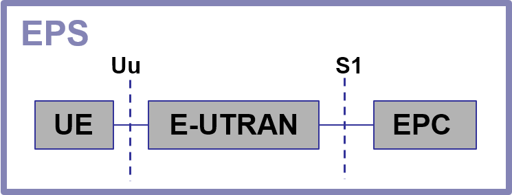
Long-Term Evolution (LTE) actually only refers to the new radio interface in this evolved phase of 3G. This radio interface is one of the most important aspects as it enables the communication link between the client device and the radio access network of the mobile telecom operator. In LTE terminology, the client device (e.g. smartphones, dongles, laptops, tablets etc.) is referred to as the 'User Equipment (UE)' and the radio access network is called the 'Evolved Universal Terrestrial Radio Access Network (E-UTRAN)', which is the successor of the UTRAN radio access network in the 3G UMTS technology. The radio interface provides considerably higher data rates in a more advanced and efficient way than other earlier large-scale mobile communications systems. In order to handle all the potential capacity that LTE can deliver, the core network side also had to be modified. This new core network is called the 'Evolved Packet Core (EPC)' or 'SAE (System Architecture Evolution)'. The complete ecosystem of the UE client device, the E-UTRAN radio access network and the EPC core network (thus including the LTE radio interface as well) is called the 'Evolved Packet System (EPS)'. When one is talking or writing about 'LTE', one sometimes refers to the whole EPS ecosystem, rather than strictly limiting to the radio interface.
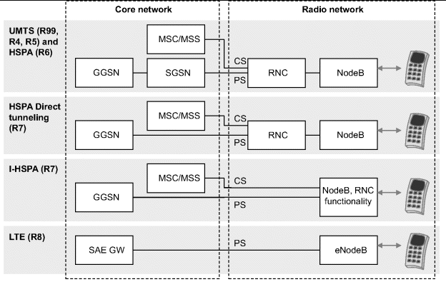
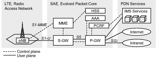
The EPS is based on a flat architecture, meaning that there is only one element type for the radio network (the eNodeB), and one element type for the core network for the data plane (the SAE GW). The figure shows the high-level architecture of LTE and compares it with the packet-switched domain of the earlier systems.
As the architecture of the Release 7 Internet-HSPA (I-HSPA) indicates, the functions of the Radio Network Controller (RNC) have already been moved to the base station, or NodeB. The packet connection chain thus contains fewer elements than in Release 6 and previous phases of UMTS and GSM. The benefit of this simplification can be seen in the shorter signaling connections and thus in smaller round trip delays, which benefits the throughput values directly.
In LTE, the eNodeB now includes basically all the functionalities that were previously concentrated on the RNC of the UTRAN system.
Radio access network
The E-UTRAN radio access network only consists of LTE base stations, which are called eNodeB or eNB (evolved NodeB). They are also the focus of this lab session. The eNodeB now includes basically all the Radio Resource Management functionalities which were previously concentrated on the additional RNC component, outside of the base stations, of the UTRAN system in 3G. In addition, the traditional tasks of base stations are off course still included in the eNodeB element. This includes the usual tasks of transmission and reception, including modulation/demodulation, coding/decoding and multiplexing/demultiplexing. eNodeB works thus as the counterpart of the UE in the radio interface but includes procedures for decision making related to the connections. As previously shown, this solution thus results in the term 'flat architecture' of 4G LTE/EPS, meaning that there are less interfaces and only one element in the hierarchy of the architecture.
Whilst also possible in other technologies, the focus on femto cells (i.e. small base stations, typically intended for home or office usage) grows with LTE technology. For LTE, these are called Home eNodeBs (HeNBs). A HeNB connects to the EPC via the (fixed) Internet access that is available within a household or company. This (typically indoor) femto cell allows for an extended coverage or to offload traffic from the macro cell.
The iMinds w-iLab.t facility that you are using via this web interface has a set of HeNBs operational. It is one of these HeNB devices you will instrument during the interactive exercises.
Core network
3GPP Release 8 defines a new core for LTE access: the Evolved Packet Core (EPC). The EPC can also be used for other access technologies like GERAN (GSM EDGE Radio Access Network), UTRAN and CDMA2000.
The Mobility Management Entity (MME) is the equivalent of the SGSN in 2G/3G GPRS networks. In the LTE/SAE network, the MME is a pure control-plane element. It initiates a direct tunnel between the eNodeB and Serving Gateway in order to deliver the user-plane traffic.
The mobile gateway functionality is divided into the Serving Gateway (S-GW) and the Packet Data Network Gateway (P-GW or PDN-GW) functionalities. These S-GW and P-GW functionalities can be implemented in the same physical node or in two separate entities. If implemented in the same physical node, then the combined entity is often called the SAE-GW. S-GW terminates the LTE core user plane interface towards the E-UTRAN radio access network. The PDN-GW allocates the IP address for the UE. PDN-GW applies policy enforcement to the subscriber traffic and performs packet filtering at the individual user's level (by performing, e.g., a deep-packet inspection). The PDN-GW interfaces with the service provider's online and offline charging systems.
Home Subscriber Server (HSS) is the IMS Core Network entity that is responsible for the management of the user profiles, and performs the authentication and authorization of the users, including the new LTE subscribers. The user profiles managed by HSS consist of subscription and security information as well as details about the physical location of the user.
Policy Charging and Rules Function (PCRF) is responsible for brokering QoS Policy and Charging Policy on a per-flow basis.
Authentication, Authorization and Accounting function (AAA) is responsible for relaying authentication and authorization information to and from non-3GPP access network connected to EPC.
Within the iMinds w-iLab.t facility, all these EPC components are integrated and realisticly emulated within a single server which interfaces as a full commercial operational EPC at mobile telecom operators.
Setup and testbed usage
General setup
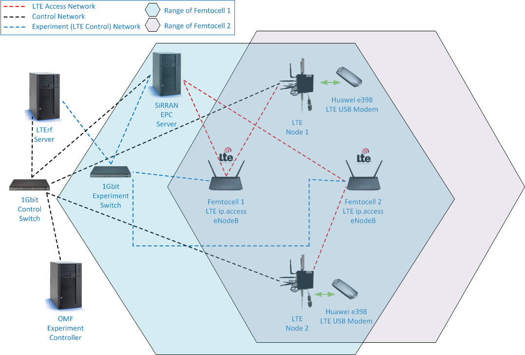
In the figure above the topology of your test hardware is displayed. For this course you will have access to two LTE User Equipment machines, each connected to an LTE Femtocell and the backend network.
The configuration of the eNodeB is done through the LTErf server, which provides an API for common eNodeB configuration tasks. Additionally, this machine will be used as an endpoint for our data streams between the LTE user node and the backend network.
Tools
The interactive exercises can be reproduced using manual tools if you wish to perform these exercises yourself on an LTE capable FIRE testbed. The two most important tools used in this session are IPerf and the LTErf OMF interface.
IPerf
To measure the UDP or TCP throughput on a wireless link, we are going to use the IPerf tool. IPerf reports bandwidth, delay jitter and datagram loss and has a client-server architecture. The tool is already installed on all systems. If you are reading this on a machine with IPerf installed, execute iperf --help to get a look at the command syntax, or visit the Ubuntu manpage for more information. We will further describe IPerf with some examples.
If you need to test the TCP throughput between two computers, you need to:
- Start a server on the first computer by executing iperf -s. If all is well IPerf tells you the TCP server is listening. If at any time you want to shut down the server, press control-c.
- Make a connection to the server you just started by logging on to the second computer and executing iperf -c Wireless_IP_first_computer; The client is now sending data to the server. Wait for the test to finish.
We now give description of the meaning of the different command line options used in iperf -c 10.10.5.3 -i 1 -u -b 10M -l 900:
-cthis machine is the client-i1 seconds between periodic bandwidth reports-utest with udp traffic-b10M for UDP, bandwidth to send at in bits/sec-l900 length of buffer to read or write (= payload of UDP-packets, if using UDP)
Please note also the difference between server and client when sending UDP traffic with IPerf. The client will print to your screen the load it tries to send, while the actually achieved throughput is displayed at the server side.
LTErf
NITLab and WINLAB (Rutgers University) have developed the first version of an OMF Aggregate Manager service, ready to be installed at any similar to NITOS testbed, that enables controlling of the ip.access LTE 245F femtocells and of SiRRAN EPC Network. Currently getting and setting values from the APs and getting values from SiRRAN EPC are supported. The values that can be changed/reported are the ones that are visible to the testbed Operator and can be used for setting up an experiment.
By sending the appropriate commands to the LTE AM service, you can change parameters on the database. For instance, in order to list all available services you will hae to issue the following command:
wget -qO- "http://lterf:5054/lterf/" | xml_pp
The command should return all the available parameters that can be changed through this service. In order to query about a specific value of an LTE AP, you will have a command similar to the following one (for example the band number that is currently in use from the AP with id = 1)
wget -qO- "http://lterf:5054/lterf/bs/get?freqBandIndicator"
The service replies with an XML formed reply. Similar to this, if the experimenter needs to change the Download link MCS profile, the command should look like:
wget -qO- "http://lterf:5054/lterf/bs/set?MCSDl=28"
For every change to take effect, a reboot is required! The reboot command is:
wget -qO- "http://lterf:5054/lterf/bs/restart"
Troubleshooting
The LTE equipment used by this online course is experimental research material that is under constant development. Stability is currently not always guaranteed, so if connectivity issues would arise, please use the following widget to reboot and reset the experimental equipment.
Restore connectivity
This widget will try to restore connectivity between the LTE dongles, Femotocells and EPC. Use the start button if the exercises appear to be unresponsive.
Executed on the lterf:
wget -qO- "http://localhost:5054/lterf/bs/restart?node=1
wget -qO- "http://localhost:5054/lterf/bs/restart?node=1
Executed on the LTE client:
reboot
#reboot dongle
AT^SETPORT="A1,A2;1,2,3,4,7,A1,A2"
AT+CFUN=4
AT+CFUN=6
#reconnect to the closest femtocell
AT+CGDCONT=1,"IP","default"
AT+CGATT=1
AT^NDISDUP=1,1,"default"
AT^DHCP?
Reboot LTE client machines
This widget will reboot the LTE client machines. Use the start button if the connectivity troubleshooting widget fails. After this troubleshooting widget completes, try the restore connectivity widget again.
Executed on the LTE clients:
reboot
Exercises
LTE throughput without interference
In these first exercises, there will only be one active LTE client, connected to one Femtocell without handovers. The following figure contains only the active components for these exercises, with the relevant IP addresses used in the different commands.
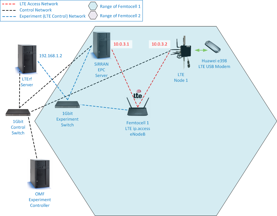
Single LTE client setup
The next three exercises allow you to inspect the effect of MCS profiles on both the upload and download speed of an LTE network. There is no need to investigate every possible value, but try to get a general feeling of the effect of the MCS profiles. Remember that each change of parameters requires the reboot of the Femtocell, taking up to two minutes.
Exercise 1-1: UDP throughput over LTE (upload)
Test the UDP throughput for the standard IPerf packet size (i.e. no packet size explicitly specified) from the LTE client to the backend LTErf server (i.e. the IPerf server runs on the backend server).
Investigate the effect on the throughput for different MCS upload profiles.
MCS upload profile:
Executed on the lterf:
wget -qO- "http://localhost:5054/lterf/bs/set?MCSUl=&&node=1
wget -qO- "http://localhost:5054/lterf/bs/restart?node=1
iperf -s -u -i 1
Executed on the LTE client:
iperf -c 192.168.1.2 -u -b 100M
Exercise 1-2: UDP throughput over LTE (download)
Test the UDP throughput from the backend LTErf server to the LTE client (i.e. the IPerf server runs on the LTE client).
Notice the bandwidth differences compared to the upload and investigate the effect of different downstream MCS profiles.
MCS download profile:
Executed on the LTE client:
iperf -s -u -i 1
Executed on the lterf:
wget -qO- "http://localhost:5054/lterf/bs/set?MCSDl=&&node=1
wget -qO- "http://localhost:5054/lterf/bs/restart?node=1
iperf -c 10.0.3.2 -u -b 100M
Exercise 1-3: UDP throughput over LTE (upload and download)
In this final introductory exercise you'll test the UDP throughput from the LTE client to a backend server and vice versa with two simultaneous IPerf streams.
Investigate if there is any form of interference between the upstream and downstream and if there is any change in the behavior of the MCS profiles.
MCS upload profile:
MCS download profile:
Executed on the LTE client:
iperf -s -u -i 1
iperf -c 192.168.1.2 -u -b 100M
Executed on the lterf:
wget -qO- "http://localhost:5054/lterf/bs/set?MCSUl=&&node=1
wget -qO- "http://localhost:5054/lterf/bs/set?MCSDl=&&node=1
wget -qO- "http://localhost:5054/lterf/bs/restart?node=1
iperf -s -u -i 1
iperf -c 10.0.3.2 -u -b 100M
LTE throughput with interference
In this final exercise you'll focus solely on the downstream performance of the LTE network, but with three important variables to investigate the effects of different types of interference. The full experimentation setup is reiterated in the following figure, including all relevant IP addresses.
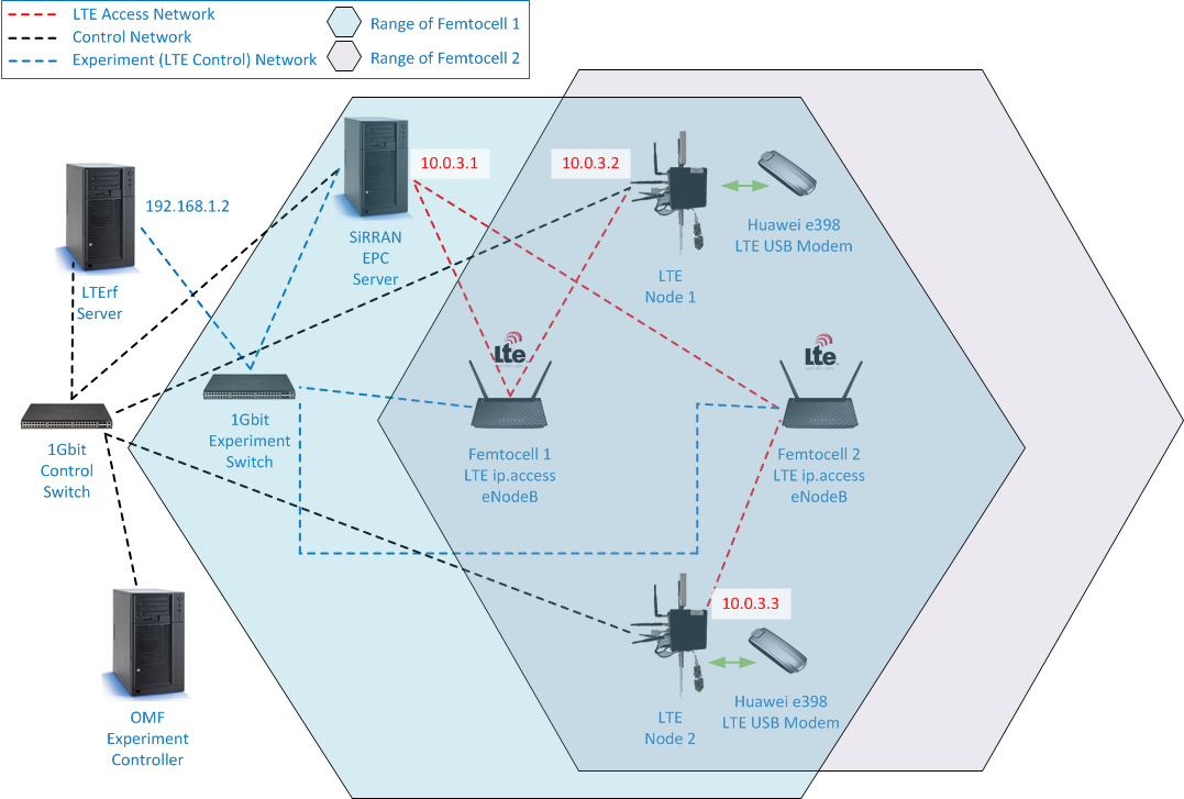
Two interfering LTE clients
As with the previous exercises, the MCS profile of the downstream can be controlled, which will only impact the Femtocell of the primary user (Femtocell 1 and LTE Node 1). There will be an interferer active on the second Femtocell (Femtocell 2 and LTE Node 2, with a fixed MCS profile of 27) for which you can control the Transmission power of the interfering Femtocell, as well as the bandwidth of the interfering download so you can investigate the differences in interference.
Femtocell 1 will be configured to use a fixed signal power of -20 that corresponds to 7dBm. You will change the signal power of Femtocell 2, where -15 corresponds to 13dBm and -26 to 0dBm.
Take your time to investigate these variables thoroughly, looking at how a different MCS profile can cope with different types of interference.
Exercise 2-1: UDP throughput over LTE with interference
Test the UDP downstream throughput under interference. There will be two IPerf streams from the LTErf backend server, one with maximal throughput to LTE Node 1, the primary user, and a second with a variable bitrate to LTE Node 2, the interfering user.
Investigate the effect of the interferer on the download of the primary user. Try find an optimal throughput by varying the MCS profile of the primary user for different types of interference (strong or weak signal, different bitrates for the interferer).
MCS download profile:
SignalPower of the interfering Femtocell
Throughput of the interfering download (Mbit/s)
Executed on the LTE client:
iperf -s -u -i 1
Executed on the lterf:
wget -qO- "http://localhost:5054/lterf/bs/set?MCSDl=&&node=1
wget -qO- "http://localhost:5054/lterf/bs/set?RefSignalPower=&&node=2
wget -qO- "http://localhost:5054/lterf/bs/restart?node=1
wget -qO- "http://localhost:5054/lterf/bs/restart?node=2
iperf -c 10.0.3.2 -u -b 60M
iperf -c 10.0.3.3 -u -b M